<?xml version="1.0" encoding="UTF-8"?>

<upm-export>
	<title>ripnet.us</title>
	<link>https://ripnet.us</link>
	<description>My page about stuff</description>
	<pubDate>Wed May 6 12:57:50 2026 / +0000  GMT</pubDate>
	<generator>Universal Post Manager 1.1.2 [ www.ProfProjects.com ] </generator>
	<language></language>
	
			<item>
			<title>Lights Controller PCB</title>
			<link>http://ripnet.us/?p=174</link>
			<pubDate>Wed May 6 12:57:50 2026 / +0000  GMT</pubDate>
			<guid isPermaLink="false">http://ripnet.us/?p=174</guid>
			<content-encoded><![CDATA[The PCB for the lights controller is in! At OSHPark, you can only order a minimum of 3.  Here they are:

<a href="http://ripnet.us/wp-content/uploads/2015/04/2015-04-23.jpg"><img class="aligncenter size-large wp-image-175" src="http://ripnet.us/wp-content/uploads/2015/04/2015-04-23-1024x576.jpg" alt="Empty Controller PCB" width="605" height="340" /></a>

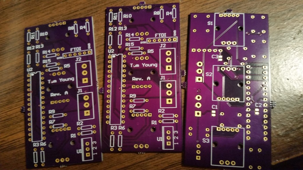
Looks like I forgot to label the ports on the silkscreen for the screw terminals. Oh well. I started soldering almost immediately. Some top components:

<a href="http://ripnet.us/wp-content/uploads/2015/04/20150423_194349.jpg"><img class="aligncenter size-large wp-image-176" src="http://ripnet.us/wp-content/uploads/2015/04/20150423_194349-1024x576.jpg" alt="20150423_194349" width="605" height="340" /></a>

&nbsp;

The rotary encoder (on the bottom/back):

<a href="http://ripnet.us/wp-content/uploads/2015/04/20150423_200511.jpg"><img class="aligncenter size-large wp-image-177" src="http://ripnet.us/wp-content/uploads/2015/04/20150423_200511-1024x576.jpg" alt="20150423_200511" width="605" height="340" /></a>

&nbsp;

All finished!

<a href="http://ripnet.us/wp-content/uploads/2015/04/20150423_200524.jpg"><img class="aligncenter size-large wp-image-178" src="http://ripnet.us/wp-content/uploads/2015/04/20150423_200524-1024x576.jpg" alt="20150423_200524" width="605" height="340" /></a>I chose not to populate the other two rotary encoders. Like I said in my previous post, I wired them in just incase my plans change.

Next I had to burn the bootloader and set the fuses. I had this rig already setup for another project and I was able to use part of the circuit for sending the bootloader.

<a href="http://ripnet.us/wp-content/uploads/2015/04/100_1700.jpg"><img class="aligncenter size-large wp-image-179" src="http://ripnet.us/wp-content/uploads/2015/04/100_1700-1024x768.jpg" alt="100_1700" width="605" height="454" /></a>I set the fuses for the 8MHz Internal RC oscillator and pushed the following command to get the chip running.
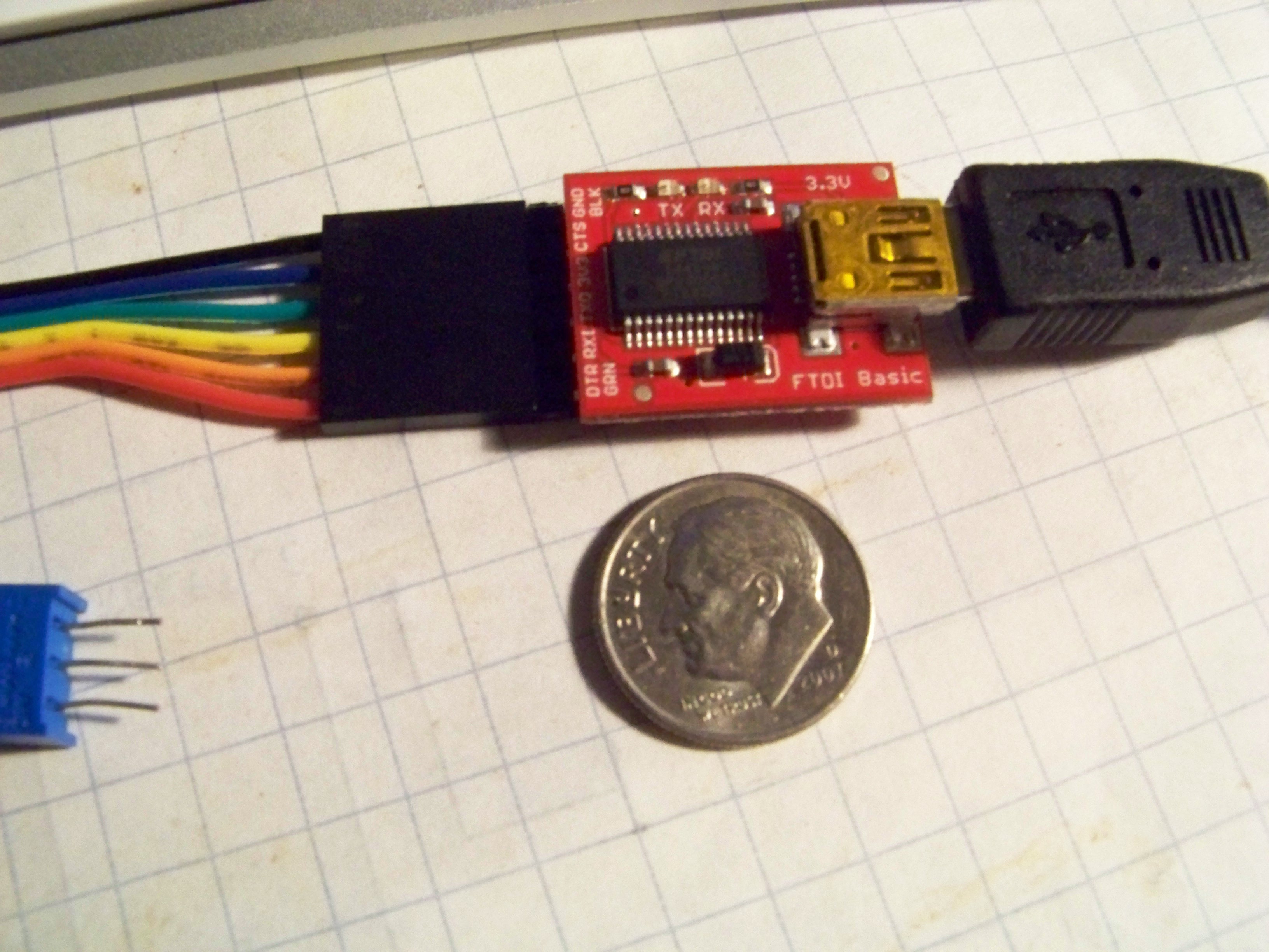
<pre class="p1"><span class="s1">avrdude</span><span class="s2"> -p m328p -P /dev/cu.usbmodem142411 -c avrisp -b 19200 -U lfuse:w:0xe2:m -U hfuse:w:0xda:m<span class="Apple-converted-space">  </span>-U flash:w:ATmegaBOOT_168_atmega328_pro_8MHz.hex</span></pre>
Then to use my trusted FTDI USB-to-Serial chip from Sparkfun. Tiny little thing...

<a href="http://ripnet.us/wp-content/uploads/2015/04/100_1701.jpg"><img class="aligncenter size-large wp-image-181" src="http://ripnet.us/wp-content/uploads/2015/04/100_1701-1024x768.jpg" alt="100_1701" width="605" height="454" /></a>

&nbsp;

In this video I power it up, upload the code, do a basic test and mount it in the wall plate. Enjoy!

<p style="clear:both"> YouTube Video: <a href="http://www.youtube.com/watch?v=EyEagA2D7pM">YouTube.com/watch?v=EyEagA2D7pM</a> </p>

&nbsp;

&nbsp;]]></content-encoded>
			<excerpt-encoded><![CDATA[]]></excerpt-encoded>
			<wp-post_id>174</wp-post_id>
			<wp-post_date>2015-04-25 13:05:48</wp-post_date>
			<wp-post_date_gmt>2015-04-25 17:05:48</wp-post_date_gmt>
				</item>
</upm-export>
