
The PCB for the lights controller is in! At OSHPark, you can only order a minimum of 3. Here they are:

Looks like I forgot to label the ports on the silkscreen for the screw terminals. Oh well. I started soldering almost immediately. Some top components:

The rotary encoder (on the bottom/back):

All finished!
 I chose not to populate the other two rotary encoders. Like I said in my previous post, I wired them in just incase my plans change.
Next I had to burn the bootloader and set the fuses. I had this rig already setup for another project and I was able to use part of the circuit for sending the bootloader.
 I set the fuses for the 8MHz Internal RC oscillator and pushed the following command to get the chip running.
avrdude -p m328p -P /dev/cu.usbmodem142411 -c avrisp -b 19200 -U lfuse:w:0xe2:m -U hfuse:w:0xda:m -U flash:w:ATmegaBOOT_168_atmega328_pro_8MHz.hex
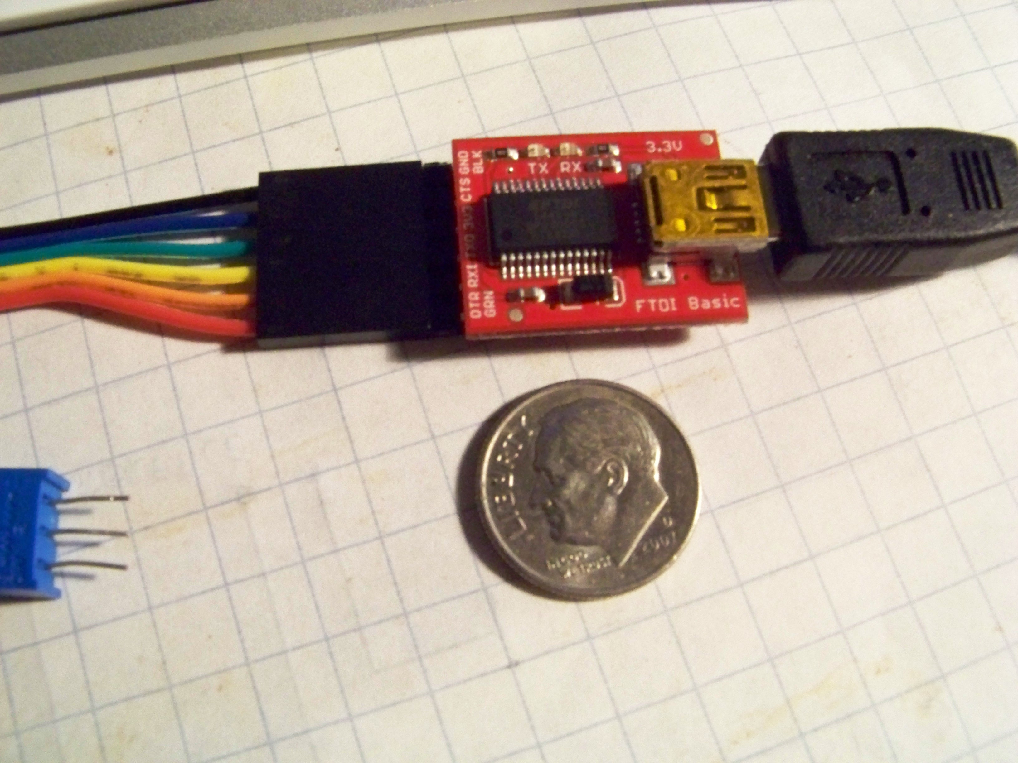
Then to use my trusted FTDI USB-to-Serial chip from Sparkfun. Tiny little thing…
In this video I power it up, upload the code, do a basic test and mount it in the wall plate. Enjoy!


Leave a Reply
You must be logged in to post a comment.