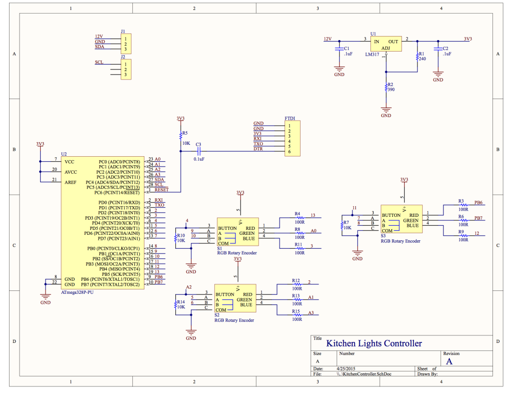
I did a quick design of the controller for the lights. It’s pretty simple: Everything connects to an ATMega328P (the heart of an Arduino) microcontroller. The RGB LEDs connect through some 100ohm current limiting resistors to the micro. If you press the rotary encoder in, you’ll notice it has a pushbutton (awesome!) so I also connected that to the micro, but those needed some pull-down resistors.
This controller will talk to the interface in the basement over an I2C bus (yes I know it’s not the best choice for the distance, but it should work just fine). The ATMega328 has I2C hardware resources built-in on ports 27 (SDA) and 28 (SCL). For programming, I opted to use an FTDI serial programming interface and not include an ICSP header. I’ll install a bootloader on the chip and just use serial to re-program it. This also gives me the ability to use the serial output for debugging.
While working on the schematic, I noticed that I had just enough ports for 2 more encoders. I don’t think I’ll end up using them, but I included them just incase.
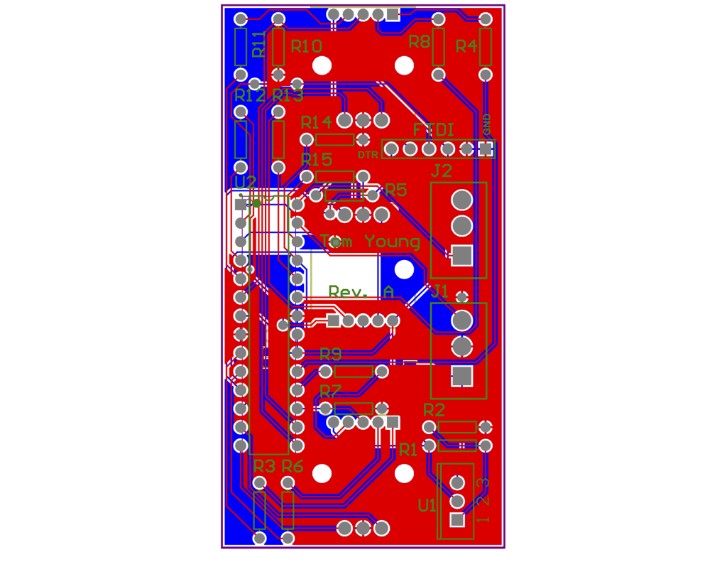
Okay, the schematic is done! Let’s turn this into a printed circuit board (PCB). I need this to fit inside an outlet box. I measured mine at 3″ x 1.5″ for a not-too-snug fit.
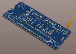
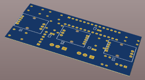
I’ll skip the boring details, but here’s what I came up with:
Next I sent this design to OSHPark for manufacture. Stay tuned!


Leave a Reply
You must be logged in to post a comment.